How to Choose the Right Safety Software?
July 9, 2021
By Martin Lalonde, Application Engineer & Technical Team Leader, Wieland Electric
Software for programmable logic controllers can vary greatly from the programming language they use to the testing and documentation tools they offer. There are a lot of them out there, with many manufacturers having proprietary software that works with their devices only. Choosing the right one can be tricky. This article looks at the requirements for safety software from the point of view of the safety standards, as well as the practical features needed to get the most out of your safety software.
Requirements from Safety Standards
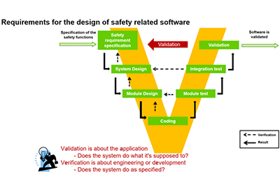
The two standards that we will consider are ISO 13849, which is for the safety of machinery. In it, there is a particular section on the V model, which describes the verification and validation process. The other standard of relevance is IEC 62061, which deals with the functional safety of safety-related Control systems. Chapter eight of this standard talks about software requirements.
ISO 13849
The V-model describes the necessary steps for designing safety-related software. The left side of the V deals with the design of the tool, if you will, and the right side of the model deals with the application of the tool to a specific use.
IEC 62061
The next thing that I want to draw your attention to is the different levels of software in the regulations. IEC 62061, Table six, describes three levels of software.
- 1. Software level A, which is a pre-assessed software platform designed for safety applications. This is where the Samos Pro Compact and its matching software Samos Plan 6 would fall under.
- 2. Software level B is a software platform for designing applications, which typically run on a PLC, but are not designed explicitly for safety applications. For example, a standard PLC programming interface from Rockwell or Siemens, that is designed for programming but not explicitly designed for safety. Additional steps would have to be taken to achieve safety.
- 3. Software level C uses another language other than the limited variability of language. An example of that might be embedded software applications that might be programmed using C or using RISC microprocessor programming at a very low level. The advantage of this would be that you probably gain some efficiencies in terms of higher response time or very defined applications. But, for most people, this is not the right solution because there is a lot more effort required in developing suitable safety software at this level.
Why use “A Level” Safety Software?
A dedicated safety software with third-party verified function blocks helps to improve the readability of the program from one user to the next.
- • It reduces faults.
- • It increases flexibility. Things like checkboxes, drop-down menus, text boxes, and so on, make it much easier to interpret and manipulate your program to do what you needed to do.
And to that point, I reference Section 8.1, IEC 62061, which says that the software shall:
- • focus on the avoidance of faults
- • produce readable, understandable, testable, maintainable, and correct software
- • it is preferable to separate non-safety functions, such as basic machine function, functionality, from safety-related control functions
Careful consideration has to be put into how you design your application, your tools, to meet those needs. By using safety software level A, the bottom part of the V is removed. By using software that’s been developed by a manufacturer, specifically for safety applications, removes or shifts the burden of module design, coding, and testing in the view model from the user to the software manufacturer. That means simplicity and expediency.
For that reason, the rest of this article will only consider software level A type solutions, and some of the tools to look for in those solutions.
Software Tools that Meet the Standard Requirements
Using the Wieland Electric software as an example, here are tools that can help achieve the compliance requirements of sections 8.1, 8.2, and 8.6 of the standard.
Verified Function Blocks
The use of third-party verified function blocks helps to achieve compliance with Section 8.1 and 8.2 of IEC 62061 by providing pre-verified logic and well-documented functions which can be interpreted later by another person. A manufacturer that uses third-party verified function blocks, can be confident that the logic in there is sound and that it complies with the relevant safety standards.
To address Section 8.6 point 2, the values should be well defined and limited. Here I will use an example of the Samos Plan configuration of analog input signals.
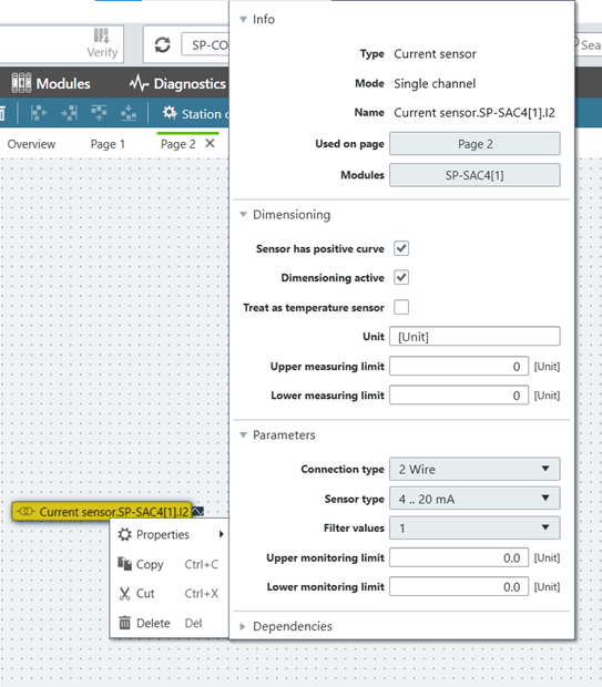
After placing the current sensor in the project, parameters such as connection type, sensor type, and limits can be set. The format is now well defined. Dimensions can also be placed and the application can be scaled.
Logic Documentation
Documentation is needed to describe the logic of each module as required under section 8.6. This is a must-have when there are multiple users, over multiple periods, that need to access the same information, or that need to jump in and do different tasks. Samos Plan, for example, provides documentation both inside and outside the software.
Inside the software, the help file provides a detailed explanation of each module, what its maximum capabilities are, and the general sense of the programming, what each parameter does, and what each input & output does. In addition, a timing diagram, allows you to view how the logic relates to one another.
We also implement a logic simulator. It is necessary to have simulation under IEC 62061 Section 8.2. This facilitates logic testing, fault simulation, and code testing. All are tools that are essential when developing a safety application.
Simulation Tools
Simulation can be done in real-time, at a slow speed, or even in fixed time steps for a detailed analysis. With superior tools to test, understand, and troubleshoot your logic, safety compliance becomes much simpler.
Another tool, the Logic Analyzer, allows you to track and generate timing diagrams for your safety project. You can choose which signals you want: inputs, outputs, and intermediate values, in the logic.
They can be charted easily and quickly to visualize causality. This can be used for troubleshooting, but also documentation so that your customers and end-users can see how things are supposed to interact.
This can be done in simulation mode when you are at the early stages of the design cycle. However, it can also be used as a signal analyzer, or a “soft oscilloscope” when you are connected to the controller. This removes the need for additional tools to troubleshoot the device when it is in the field. Paired with remote diagnostic, remote signal analysis is possible. Validation is also easy because signals can be recorded on-site. In addition, long-term data can be stored for easy troubleshooting.
Finally, a force mode function, much like a simulation, allows for the control of the values of inputs and overrides them so that you can simulate things that are happening in your machine and recreate situations that might be otherwise difficult to recreate.
Force mode is done while connected to the controller and used to override the inputs. It is in the software, but the outputs are very real; the controller will drive machinery based on the inputs provided. The inputs can be forced, high and low, to test machines in scenarios that may otherwise be difficult to realize, such as simulating sensors that are missing. It can also help to avoid situations where you might decide to bypass the safety sensor by putting in a jumper wire.
Being built-in to a safety software, the force mode itself needs to comply with certain safety principles including limiting the time that you can remain in this mode. This prevents you from having a permanent override to a safety function and is much safer than using a jumper wire, which can easily be forgotten.
Documentation & Reporting Tools
A huge part of designing a safety application is of course documentation and reporting. The regulations demand not only that safety checks have been done, but there needs to be proof of those checks and tests. Having tools for report generation makes life much easier, and it is a must for any safety software that you are considering.
A one-click report generation tool, such as the one on the Samos Plan 6, allows you to generate a report that includes all of the necessary information with one click. This report gives you information on the logic, the software version, hardware versions, serial numbers, and wiring. If there is a fault history, you have that documented as well.
Section 8.1 and 8.12 require that there should be the management of software versioning during testing. This report provides a CRC Number or checksum. Any changes you make to the software will change the CRC Number, allowing you to quickly and easily identify which version you are looking at.
If you are designing software level B in software level C, these tools do not exist. So you have to be very meticulous to document everything and inherently you’re going to end up with some errors. It is also a lot more burden on the developers and programmers to ensure that the application is complying with the relevant safety standards.
So far, these are all obvious things for compliance, but you have to look a little bit beyond the standards because there is also an expectation that most A-level software from reputable manufacturers will meet a lot of these requirements.
So, how else can you differentiate similar software to decide which one is right for you?
Additional Safety Software Requirements
Usability
Since you will be using this a lot it is worthwhile to demo the software and determine how easy it is to use, how comfortable, and how fast it is. Some things to look for:
- • Can you have multiple screens?
- • Can you configure the windows and which functions show up first?
- • Is it easy to change from one type of device to another? For example from a desktop computer to a tablet?
Reliability
How reliable is it? Are there any tools to reduce errors and improve commissioning efficiency?
Security & Intellectual Property
Security and intellectual property protection are not required but they are a huge part of the development of your machine. The safety software you choose must address this.
For example, some security controls allow you to limit, through passwords, access to the controller, the logic, and what changes a user can and cannot make. This enables both the safe and efficient operation of the machine without necessarily compromising its reliability by having unauthorized access by somebody that might not be qualified.
Next, you should consider tools to protect your intellectual property. Is your device protected against cyber tampering? By connecting to your controller remotely, you could be exposing yourself to possible cyber tampering. Tools such as code keys make it so that changes and downloads of the software can only happen with a USB that carries that code.
There are also tools to prevent program duplication. Can you lock the project to a specific station or controller? Alternatively, can you lock that controller to a specific logic project? This further prevents unauthorized changes to your machine.
Global Support
Global support is another factor to consider. If remote connectivity is important for your project then you need to make sure that the software supports that (e.g. Ethernet).
Is it possible to update the program from a distance to facilitate remote support? Can you tunnel in to do troubleshooting?
Other features you might consider are:
- • the types of data it can handle
- • whether or not it can read/write via fieldbus
- • multiple signal requirements
- • discrete inputs and outputs
- • whether it can handle analog values
- • or high-speed inputs
Starting from the software requirements defined in the safety standards, look for a safety program that has verified function blocks and robust documentation and simulation tools. This will ensure compliance with safety laws and regulations and make it easier to make changes to your application down the line. By paying attention to the usability, reliability, security, and global support features of safety software, you can ensure you have an application that is easy to troubleshoot and maintain over time, and multiple change cycles.
Download the Samos Plan safety software here: https://www.wieland-safety.com/programming-software/