Application Notes: Voltage Stabilization
December 10, 2020
In this article, we will discuss a KEB drive feature called Voltage Stabilization. This post is part of a series that highlights different KEB drive features and how they can be utilized to optimize motor performance. Previous post topics include:
Input Voltage determines VFD Output Voltage
One of the many benefits of using a variable frequency drive (VFD) to control an electric motor is the ability to adjust the voltage output to the motor for optimal efficiency.
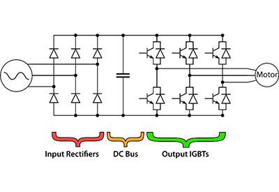
A VFD rectifies the AC input voltage to a DC voltage across the DC bus capacitors. The VFD then uses a PWM output to convert this DC power into an AC output to the motor.
When operating the VFD in an open loop mode, the output voltage and frequency is based on a defined Volt/Hz curve in the VFD. The available AC voltage output of a VFD is dependent on the DC bus voltage level. And the DC bus level is dependent on the AC input to the VFD.
Thus, any fluctuation in the AC input voltage may cause the output voltage to the motor to fluctuate as well. Normal voltage deviation from the nominal input usually does not result in any noticeable effect on motor performance. However, extreme voltage variations to the motor (undervoltage or overvoltage) can cause extra motor heating and premature failure.
In the cases where large input voltage fluctuations may occur (weak mains, generator power), having the ability to stabilize the output voltage to the motor independent of the input AC main fluctuations, allows the system to run more efficiently and increase the lifetime of the motor windings.
What is Voltage Stabilization?
And when should I use it?
KEB VFDs incorporate a function called Voltage Stabilization into the parameter settings which allows the VFD to stabilize the output voltage to the motor based on the motor requirements.
An example when Voltage Stabilization would be used is if a motor has a rated voltage lower than the input voltage to the drive. The KEB VFD is designed for an input voltage range of 480±10%. Thus, the input voltage may be up to 528VAC. An input voltage near the top end of the voltage range can happen on a voltage system with weak mains. Maybe the voltage level is closer to nominal while the mains system is loaded, but the voltage can increase when the overall line load is reduced. A typical scenario is when a high voltage fluctuation happens during the evening when most machinery has been turned off.
In this case, if the motor rated voltage is 460VAC (60Hz) and there is no stabilization of the output voltage, when the input voltage increases, this can effectively increase the Volt/Hz curve slope which would increase the output voltage to the motor at a given output frequency. The sub-optimal higher voltage would result in higher motor current which leads to increased motor heating. The increased current and heat can have a negative impact on the lifetime of the motor windings and the performance of the motor.
The KEB Voltage Stabilization function allows the user to define what the output voltage to the motor will be at the rated output frequency. The Voltage Stabilization function then keeps the output voltage to the motor fixed to the proper Volt/Hz curve independent of any input voltage fluctuations, and consequently DC bus fluctuations in the drive. In the case where the input voltage increases above the rated voltage of the motor, the KEB VFD Voltage Stabilization function keeps the voltage output to the motor limited to the Volt/Hz curve based on the entered values in the KEB VFD.
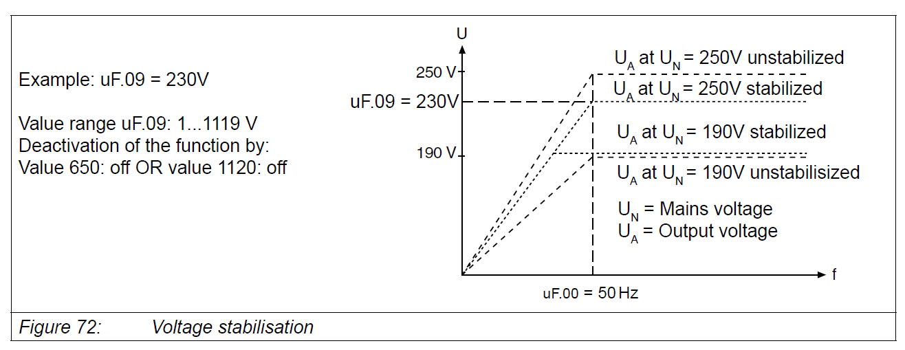
Enabling Voltage Stabilization results in an optimal V/Hz curve even during situations with a high input voltage to the drive.
In the example case above (Figure 72), the output to the motor is set to 460VAC at 60 Hz. Without the voltage stabilization activated, the output to the motor would be increased by the ratio of the input voltage to the rated voltage of the motor. In this case, it would be increased by a ratio of 528VAC/460VAC = 1.15. So if the motor was running at 30 Hz, the output voltage should be 230VAC. Without the voltage stabilization, the output voltage to the motor would be 230VAC*1.15 = 264.5VAC.
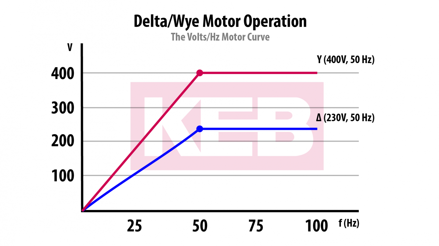
The same situation above occurs when running a motor rated at lower voltages than typically found in the United States. For example, a European motor rated at 400VAC/50Hz or 380VAC/60Hz. In this case, the voltage stabilization function allows the user to limit the output voltage at the specified frequency to match the Volt/Hz curve of the motor being controlled by the VFD.
Performance Results
When the KEB VFD Voltage Stabilization is activated, the Volt/Hz curve for the motor is defined in the VFD software. If the input voltage drops below the rated voltage of the motor, the VFD will still follow the correct Volt/Hz curve until the output voltage limit is reached. When the required output voltage to the motor equals the input voltage, the output voltage to the motor will remain at this level. If the Voltage Stabilization is not activated, a reduction in the input mains voltage would result in the slope of the Volt/Hz curve being reduced which would result in a lower than required voltage at the motor terminals. The lower voltage can result in increased current and heating of the motor and reduced motor performance.
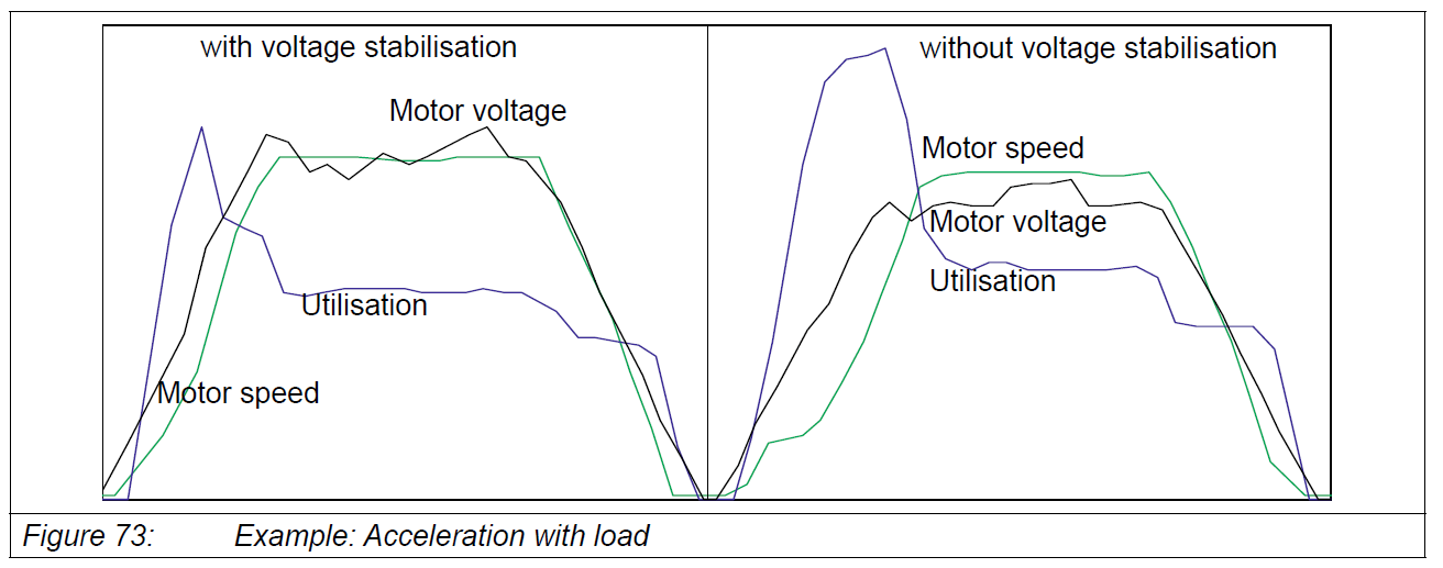
In this case (Figure 73), the use of Voltage Stabilization results in lower current utilization.
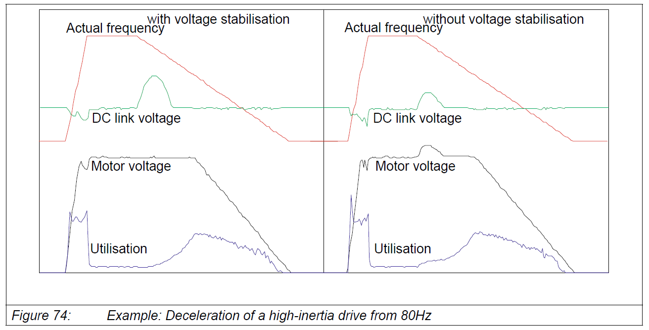
Voltage stabilization provides an optimal voltage output, especially with overhauling loads (see Figure 74).
Improve Motor Shaft Performance
By utilizing the KEB VFD Voltage Stabilization function, applications can be set up to run at the highest efficiency possible. Increasing motor performance and lifetime allows machine builders and end users to get the most out of their investments.