Three Ways In Which IO-Link Sensors Minimize Downtime

May 18, 2021
IO-Link technology was created in response to three consecutive challenges. The first was the tendency of manufacturers to use whichever I/O system protocol they liked best, causing the devices to not “play well” with those of other manufacturers. To mitigate this issue, some manufacturers began designing fieldbus interfaces into their sensors and actuators.
This solution worked well for some time, but before too long, the size of automation equipment shrunk to the point where fieldbus interfaces would no longer fit into sensors. This second challenge was compounded by a third tendency for automation equipment to become more complex overall, necessitating more types of data collection.
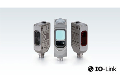
Enter IO-Link, an open network standard point-to-point communication protocol that enables bi-directional data exchange from IO-Link-enabled sensors and other devices. This powerful solution has helped scores of manufacturers increase their data availability, reduce wiring effort, improve machine diagnostics, and easily reconfigure device replacements.
Let’s take a look at a few ways that sensors with IO-Link functionality can help banish the ultimate manufacturing bogeyman: downtime.
1. IO-Link increases data availability.
IO-Link gives manufacturers access to more machine- and process-related data from sensors beyond a simple ON/OFF reading. This data – which might include temperature, measurement, or voltage output readings – can be either analyzed in real time or stored for more extensive trend analysis in the near future.
Because changes in output performance, temperature or other forms of data can correlate to machine health, IO-Link sensors support predictive maintenance strategies that maximize uptime.
2. IO-Link makes device replacement easy and simplifies wiring.
IO-Link provides automated parameter reassignment functionality to let users import parameter values from IO-Link masters into the new sensors that are being used to replace old or damaged ones. Additionally, no special wiring is needed for IO-Link devices. In fact, the protocol reduces inventory costs by cutting down on the types of cord sets required for sensors.
These two features make it quick and easy to replace devices and minimize the amount of downtime required for product changeovers.
3. IO-Link enables remote monitoring.
Operators don’t need to be close to IO-Link devices to read and change their parameters. This can be done remotely via the control system software, making configuration and commissioning time shorter than ever. For changeovers, operators can dynamically alter the parameters from the control system at any point.


