Steppers Surpass Servos in Many Motion Control Applications
July 15, 2021
By Joe Kimbrell, Product Manager, Motion Control, AutomationDirect
Industrial machinery commonly incorporates many moving elements which need to be driven with precision and force. Designers can choose from pneumatic options to save cost, or hydraulic alternatives when ultimate force is needed. However—when accuracy, speed, power, durability, and operating costs are all considered—the most common motive force is usually an electric motor. The ability for an automation system to positively command the position, velocity, and acceleration of moving systems, especially using some form of electric motor, is generally called motion control.
Standard AC induction and DC motors are good for on/off and continuous operation at a fixed speed, or even varying speeds. However, the intermittent operation and meticulous positioning targets and velocity/acceleration profiles used by automated machinery calls for a more capable technology. Servo controllers, drives, and motors can deliver exceptional performance in this regard, but their complexity drives up the cost of materials and design.
For many applications, a stepper motor solution occupies the sweet spot of providing the required performance, but at a much lower cost than servo solutions. This white paper identifies the features and benefits of DC stepper motor solutions and introduces a newer high bus voltage style which makes the technology viable for many more applications.
Electric Motor Options
Implementing motor control of any type usually entails specifying a motor, drive, controller, and power supply. Many times, some of these functions are combined in a component or can be simplified. For instance, an AC induction motor may be driven and controlled by a simple on/off contactor and powered from AC facility power.
However, a servo motor will require a drive, which is usually separate but may be physically attached to the motor. The drive may have on-board motion control and sequencing capabilities, or it may be commanded by a separate higher-level motion controller or a programmable logic controller (PLC).
Several motor technologies are suitable for various aspects of machine, equipment, and process automation.
• AC Induction Motors: Useful for a wide range of size and horsepower ranges where precise operation is less important. Typically used for single-speed operation, but adjustable speed is possible with a variable frequency drive (VFD).
• DC Motors: Excellent torque at low speed, and reasonable speed control is achieved with the required DC drive.
• DC Stepper Motors: For lower speeds and small force requirements, stepper motors provide better control resolution than standard AC or DC motors because the stepper motor is commanded by pulses to move in small discrete steps, which can happen quite quickly.
• High Bus Voltage Stepper Motors: Like DC stepper motors, but because the drive accepts AC power and uses it to generate a higher DC bus voltage, this style has higher speed and torque capabilities than their lower voltage counterparts. However, as with DC steppers, torque falls off as speed increases, and stepper motors typically work best below 1,000 rotations per minute (rpm).
• Servo Motors: When combined with a servo controller and servo drive, servo motors provide high speed with full torque throughout the speed range, and ultra-precise control of position, velocity, and acceleration—even through complex profiles. However, the hardware costs and configuration effort are among the highest for motor technologies, up to four times the expense of implementing a stepper.
Many times, it is possible to mix and match motors, drives, and controllers supplied from different vendors if electrical ratings and compatibility are observed. However, many users find that for servo motors, it is most effective if they select products from within a single vendor portfolio for best compatibility and support.
AC induction and DC motors are considered the easiest to install and maintain, while both steppers and servos present more challenges because of additional hardware, design requirements, and installation effort. However, steppers and servos are usually necessary to obtain true motion control performance.
Motors used for motion control may operate loads directly or via gearboxes, toothed pully-and-belt (not smooth or v-belt type), rack-and-pinion setups, or other mechanisms to drive the target equipment elements in a rotary or linear fashion. These positive mechanical motion transmission methods ensure that motor motion is directly related to the load motion. Some motion applications work fine with limited position feedback, or even no feedback. However, for better reliability and higher-performance solutions the system will work best with motor feedback.
Open versus Closed Loop Motion Control
Open loop motor operation is when a motor is commanded to run by a starter or drive, but the motor position or speed are not monitored directly, so there is no feedback regarding accuracy. Closed loop motor operation is achieved by installing a sensing device on the motor and connecting it to the drive or controller, providing operational feedback enabling the system to better control the motor speed or position.
Open loop control is appropriate for applications not requiring positive confirmation of motor speed regulation or position. Sometimes the control system externally monitors the driven equipment to provide some degree of feedback. An example is a crane gantry which moves forward and backward and has electrical limit switches at each end of travel. A PLC could control the motor forward and backward and stop it at the end of the mechanism.
Closed loop control becomes necessary for accurate motion control and machine applications, such as for mechanisms on a packaging machine where carton folding, product placement, and labeling elements must be precisely controlled to reach a position.
It is possible—and becoming common—to operate stepper motors as closed loop. On the other hand, servo motors are operated as closed loop by their nature.
Most stepper motors reside in a middle ground, with better position command than AC induction and DC motors, but without the positive closed loop feedback of servo motors. In fact the biggest difference in the application of stepper and servo motors is often open versus closed loop feedback.
Note that there are ways to add feedback so that stepper motors can be implemented as closed loop systems. Furthermore, some more advanced stepper motors with integrated drives are becoming available and offer a form of closed loop control.
Even though stepper motors can be considered as a low-cost motion control alternative compared with servo motors, steppers have some other advantages. Stepper motors have no jitter/dither at zero speed. For applications without a constant load from gravity or some other force, some stepper drives may have an idle current reduction option which saves energy and reduces heading when the shaft is at standstill.
In operation, each path of travel for motion control applications is called an axis, whether it is rotational or linear. Sometimes multiple axes need to be coordinated together, such as the X, Y, and Z positioning of a product pick-and-place gripper. For high-end multi-axis motion control—possible with steppers, but a function which servos excel at—it is best to have the intelligence located at the motion controller. Motion controllers can include built-in path planning, also called an indexer, for these applications. However, there are many single axis applications where steppers provide an optimal solution.
Stepper Specifics
Stepper systems are usually commanded by a pulse train. Each pulse into the drive directs the motor to move one step, and there are commonly 200 steps for each 360-degree revolution, so each step represents 1.8 degrees of movement. For each application, users must consider the step mode, controllers, step pulse and signal types, position verification, and motor sizes.
Step Mode
In full-step mode, the controller would need to generate 200 steps (pulses) to achieve one complete motor revolution. However, most users do not use full-step mode because it is a little coarse due to the stepwise cogging effect.
Instead, many users select half-step or quarter-step modes, which respectively double and quadruple the number of pulses needed for a complete revolution. Some stepper drives support a micro-step mode which could call for up to 50,000 steps for a complete revolution. Typical microstepping drives have several different settings available for the microstepping resolution.
The next consideration is how fast a controller can generate pulses. If a controller can produce 100,000 pulses per second (100kHz), then the following modes could generate speeds of:
- • 400 steps/rev (half-step): 250 rps, or 15,000 rpm
- • 800 steps/rev (quarter-step): 500 rps, or 7,500 rpm
- • 10,000 steps/rev: 10 rps, or 600 rpm
- • 50,000 steps/rev: 2 rps, or 120 rpm
There are inherent tradeoffs between accuracy, smoothness, speed, and force, with the main tradeoff being between resolution and speed. Finer step modes improve accuracy and smoothness, but eventually limit maximum speed due to controller pulse generation or drive response constraints.
Another consideration inherent to stepper motors is that available torque is reduced as speed increases, so designers must balance the transmission arrangement and motor speed.
Stepper Controllers
A stepper controller generates commands detailing the distance a motor should rotate, and how fast it should do so. Some motion examples, progressing in complexity include:
- • Move at a fixed velocity
- • Move a number of steps and then stop
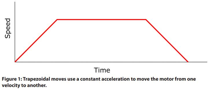
- • Accelerate from one velocity to another; known as a linear move
- • Move a number of steps from one stopped position to another, first accelerating to a target velocity then decelerating back to zero speed at the target position; known as a trapezoidal move (Figure 1)
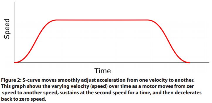
- • Accelerate from one velocity to another; known as an S-curve move (Figure 2)
Basic stepper drives are not intelligent, they simply receive a high-speed pulse train from a controller and amplify it to the voltage needed to operate the motor. More capable stepper drives include the control intelligence to perform advanced functions, and they may incorporate communication protocols so they can interact with higher level automation components.
Some controller options are to use a PLC, micro-controller, or PC with high-speed digital outputs—or even a dedicated motion controller—to command a basic stepper drive. The controller orchestrates all the logic and motion activities, and the drive simply produces the necessary voltage pulses to operate the motor. The PLC option is attractive because many machines are already automated by a PLC, so the motion actions can be tightly integrated with the controller program, while the stepper drive costs are minimized. PLCs fitted with high-speed discrete output cards are an effective way to implement this type of single-axis machine control.
Step Pulses and Signals
High Speed Pulses
The high-speed pulses a controller sends to a stepper drive must encode the direction and the pulse frequency, which together define the desired motion. There are three main types:
- • Pulse/direction (this is the most common method)
- • Clockwise (CW) / counter-clockwise (CCW)
- • A/B quadrature (sometimes used for encoder following because this signal is often used by encoders)
Designers must select compatible controller and drive pulse methods. Furthermore, the pulse signal electrical characteristics may be open collector, line driver, or push-pull. Again, these must be coordinated through direct selection, or by using appropriate signal conditioners.
Analog Signals
Stepper motors are predominantly employed when users need to command a motor to travel to a known distance or to a given position, but they can be used to provide commanded rotational velocities. The user can simply select a drive which will accept a standard industrial analog signal, such as 0-10Vdc or 4-20mA, and the drive will generate its own pulse train. For instance, 4mA could correspond to 0% of rated motor speed, and 20mA could correspond to 100% (or whatever maximum speed is desired).
This form of control is not as elegant or precise as a pulse train signal, but it is often a good fit for continuously rotating equipment, like a small turntable or conveyor. In these cases, a designer can specify an oversized stepper drive (to accommodate a larger margin for torque) and drive equipment directly, as opposed to choosing a DC drive and associated motor and gearbox.
Discrete Inputs and Digital Communications
The most intelligent stepper drives have a built-in mini-controller, which can be programmed with adjustable parameters and preconfigured moves triggered by simple on/off signals, or initiated by more advanced communications from a higher-level controller. This method effectively offloads the higher-level controller because advanced point-to-point moves are being handled directly by the intelligent stepper drive.
Discrete signals are usually 24Vdc or dry contacts. Some intelligent stepper drives can work with popular industrial networking protocols like:
- • ASCII / Serial
- • Modbus RTU or Modbus TCP
- • EtherNet/IP
- • PROFIBUS or PROFINET
While these industrial protocols are fast and allow a large amount of data to be communicated, there may be some concern the timing is not fast enough to execute real-time moves with enough precision. In these cases, a hybrid approach is possible where the industrial protocol is used for a higher level controller to preconfigure parameters and move details in the smart stepper drive, while a discrete control output wired to a drive input initiates the critical move.
Homing and Position Verification
Regardless of the controller type and signaling methods, a stepper motor can only perform accurate positional movements after the controller has learned the home position, a procedure called homing. In addition, a cyclic position verification may be used to confirm accurate movements during subsequent operation.
A homing procedure serves a function to establish a position baseline for future movements, much like a weigh scale which must be zeroed before determining the true weight of subsequent payloads. For stepper controllers, the pulse count totalizer is zeroed at a known home location, with all future moves tallied relative to this location.
Homing usually must be performed upon equipment power up and may be executed intermittently as needed thereafter, and this activity may take a little time to accomplish.
Position verification is a similar activity but is generally a quick check used to confirm whether the position is as expected. If a problem is detected, then it would be necessary to perform a homing procedure to re-establish the positioning baseline. Rigorous applications would demand frequent position verification, perhaps once (or more) for each cycle or operation.
One way to accomplish homing is by installing a position switch at a known location on the driven mechanism. When the stepper controller/drive combination is ready to learn the home position, it travels quickly to the expected position. As soon as the position switch is triggered, the controller zeroes the pulse count totalizer, effectively learning the new home position. An enhancement of this procedure to improve accuracy is driving the equipment slowly off the home position switch and recording when the switch is un-triggered, yielding an even more accurate home location. Position verification is similar, but position switches may be inspected at one or more locations during normal travel of the equipment through an operating cycle.
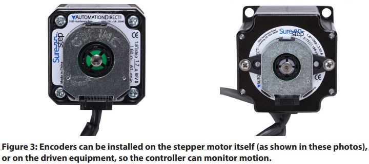
It is also possible to install an incremental or absolute encoder on the driven equipment, or on the stepper motor itself, and connect it so the controller can monitor motion activities (Figure 3). Encoders used in this way provide closed loop operation to verify position. They enable the controller to detect (and correct) slippage, such as when driving webs, or they can identify an overloaded or stalled motor condition so that the automation program can act or notify operators. In velocity control mode, an encoder verifies the proper operational speed. Homing usually must be performed upon equipment power up and may be executed intermittently as needed thereafter, and this activity may take a little time to accomplish.
Position verification is a similar activity but is generally a quick check used to confirm whether the position is as expected. If a problem is detected, then it would be necessary to perform a homing procedure to re-establish the positioning baseline. Rigorous applications would demand frequent position verification, perhaps once (or more) for each cycle or operation.
One way to accomplish homing is by installing a position switch at a known location on the driven mechanism. When the stepper controller/drive combination is ready to learn the home position, it travels quickly to the expected position. As soon as the position switch is triggered, the controller zeroes the pulse count totalizer, effectively learning the new home position. An enhancement of this procedure to improve accuracy is driving the equipment slowly off the home position switch and recording when the switch is un-triggered, yielding an even more accurate home location. Position verification is similar, but position switches may be inspected at one or more locations during normal travel of the equipment through an operating cycle.
It is also possible to install an incremental or absolute encoder on the driven equipment, or on the stepper motor itself, and connect it so the controller can monitor motion activities (Figure 3). Encoders used in this way provide closed loop operation to verify position. They enable the controller to detect (and correct) slippage, such as when driving webs, or they can identify an overloaded or stalled motor condition so that the automation program can act or notify operators. In velocity control mode, an encoder verifies the proper operational speed.
Some encoders have a built-in marker pulse, also known as a Z-pulse, which identifies a known location in the rotation. In some applications this marker pulse can be used in combination with an external switch to home the stepper motors. Most encoders with a marker pulse come from the factory configured at a fixed location, so the relative location must be initially learned when it is installed and commissioned on the equipment. Some newer encoders feature a configurable marker pulse which can be set as desired during installation, with no hardware/physical adjustment required.
Related to position verification is the fact that many motion systems require end-of-travel and/or over-travel limit switches, which the controller can monitor in operation to prevent stalling the motor or damaging equipment when mechanical limits are reached. These switches may be alarmed during operation to indicate a motor has stalled in operation and lost synchronization, or they may initiate a position verification operation.
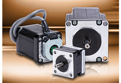
Motor Sizes Stepper motors are available in many standard NEMA sizes, and motors in the range of NEMA 14 up to NEMA 34 are commonly used. They are compact in size, usually no more than a few inches square, which makes them easy to design into machinery. Even larger stepper motors are available, such as a NEMA 42 offering the torque of a 7.5 HP AC motor, although these larger motors have much lower rated maximum speeds. One industry rule of thumb is to size stepper motors and drives so that the expected load uses only 50% of the available torque, to avoid potential stalling conditions. This is because steppers don’t have overload capability, compared with AC induction and servo motors which can handle brief overloads with now problem.
Conclusion
AC induction and DC motors are well-understand as a reliable and basic motion control method. Similarly, most designers know that servo motors are a high-performance solution for the most demanding motion control applications, such as robotics.
Stepper motors can be an advantageous choice for many applications, and when they are suitable, they will be the most cost-effective option. For low-force applications where accurate single-axis or limited multi-axis motion control is needed, stepper motors and drives used in conjunction with position switches and/or an encoder will reliably operate machinery at perhaps 25% the cost of servo motor systems.
Suppliers like AutomationDirect offer an online stepper selection tool (https://www.automationdirect.com/selectors/steppers), customer assistance, and a wide variety of associated parts and technologies to help users implement the best solution for their application.
![]()
![]()