Versatility, Precision and Short Lead Times: The CRD MR Rotary Indexer
December 11, 2020
Whether due to a bustling economy, reshoring, better technology or a skilledlabor shortage, manufacturers are automating more than ever before. According to ASSEMBLY magazine’s annual Capital Equipment Spending Survey, 89 percent of U.S. factories employed manual assembly processes in 2009, while only 17 percent used fixed automation. A decade later, those numbers are decidedly different. In 2018, 77 percent of factories employed manual assembly processes, but 31 percent used fixed automation.
What’s more, 29 percent of factories plan to purchase multistation automated assembly systems in 2019. That compares with 18 percent in 2018, and it’s the highest percentage since 2009. All totaled, sales of multistation automated assembly systems are projected to increase 8 percent in 2019, to $800 million.
The automation boom is welcome news for systems integrators, but growing demand for automation in the U.S. and worldwide has also led to a problem: Lead times for indexers, linear actuators, robots and other automation components have increased dramatically. Depending on the size and complexity of the component, delivery times for linear slides can range from 20 to 26 weeks; robots can range from 14 to 20 weeks; and indexers can take eight to 12 weeks.
“The typical lead time on certain product groups has increased from 50 to 100 percent in the past year,” says the purchasing manager for a major U.S. systems integrator. “This is extremely problematic for us at times. We operate with no onhand inventory, so it’s critical to have accurate deliveries from our supply chain. When [we can’t get components in a timely manner], it affects our lead time commitments to our customers.”
Lead times are a big deal for systems integrators, since designing and building an automated assembly system can take a while. A simple project might take 12 to 14 weeks. A complex one could take 48 to 52 weeks. With a large project, approximately 25 percent of the total project time will be spent on mechanical and electrical design and acquiring long-lead-time items. Another 25 percent will be spent actually building the machine; 25 percent will be spent debugging the machine; and 25 percent will be spent on final run off, tear down, shipping, installation and training. Anything that can shorten that timeline—and thus, help a customer get its product to market faster—is welcome.
It’s not surprising, then, that delivery time is a major consideration when choosing suppliers of automation components. According to a recent market research study conducted by ASSEMBLY magazine, 82 percent of engineers rank delivery time as an important factor when selecting components for an automation project. Only quality (96 percent) and service and support (93 percent) rate higher. Interestingly, price is a distant fifth.
New Indexer Ships in Three to Four Weeks
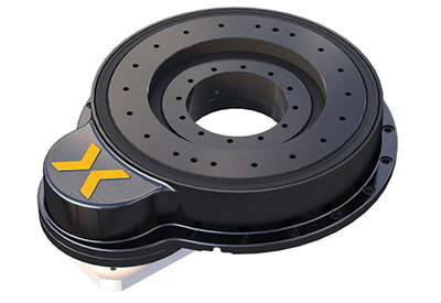
Nexen’s new CRD MR (Compact Ring Drive Motor Ready) products build on the company’s successful CRD line of precision rotary indexers. CRD MR line maintains the benefits of the company’s patented precision roller pinion drive design—zero backlash, high precision, high torque, high acceleration, smooth motion and low maintenance—while delivering significant new benefits.
One of those benefits is flexibility. Until now, the CRD indexer was available in three configurations, giving engineers options for high speed, high torque or both, depending on the application. The CRD PL is equipped with a highprecision planetary gearhead, offering high torque, high speed, low backlash and a flexible gearhead ratio. The CRD HG has a harmonic gearhead, which provides high torque, low speed, zero backlash and a high gearhead ratio. The CRD DD is equipped with a direct-drive motor, which offers high speed, medium torque and zero backlash.
The CRD MR line gives engineers a fourth option: to drive the indexer with their own motor or gearbox. That provides two big advantages: It lowers the cost, and it enables Nexen to deliver the indexer in just three to four weeks—half the time of a traditional cam-driven indexer.
“With our customizable input, the CRD MR product can accommodate a wide array of applicable motors and shaft-output gearboxes,” says Broc Grell, applications engineer at Nexen.
A high roller-pinion-to-gear ratio allows engineers to drive the system directly with a servomotor or even a stepper motor, eliminating the cost of a gearbox. For high-load applications, the customer can drive the system with a gearbox and motor. Additionally, the gear-to-pinion reaction loads are fully supported, so the motor or gearbox shaft is not subjected to radial loading. This eliminates the need for costly high output capacity reducers in high-load applications. All of these features reduce engineering and installation time.
“Increasing the pinion-to-gear ratio allows us to drive higher inertial loads on the output with a smaller motor on the input,” says Isaac Klaehn, engineering manager for motion control products at Nexen. “That gives a lot of flexibility to the customer.”
For example, the CRD PL 250 has a pinion-to-gear ratio of 3.8-to-1, while the CRD MR 250 has a pinion-to-gear ratio of 12.5-to-1. Since there’s an inverse square relationship between the gear ratio and output inertia, increasing the ratio from 3.8 to 12.5 is a big deal. It’s much better to divide a 50-kilogram load by 156.25 (12.52 ) than 14.44 (3.82 ).
“When the ratio from the input to the output is increased, the input speed must also increase to maintain the same output speed,” says Klaehn. “Design efforts with the new product’s development maintained the peak speed of the indexer. Our new CRD MR indexers have the same capacity and speed as the original models, even though the ratio was increased.”
Like the original CRD indexers, the CRD MR indexers have a large, open center, so engineers can mount cabling, robots, inspection cameras and other devices in the center of the rotating plate. That saves space and makes for an overall efficient and “clean” machine design.
Roller Pinion System An Alternative to Traditional Linear Drive Systems Alternatively, engineers don’t have to put anything in that open space. “We’re quoting a project right now that will have multiple stations around the indexer. When the part is finished, it will be ejected to the inside of the indexer instead of the outside,” says Klaehn. “A conveyor will pass underneath the indexer to take the finished parts to a packaging line.”
Three Models and Three Sizes
The CRD MR line is available in three sizes: 150, 250 and 350. The latter two sizes are “drop-in” replacements for Nexen’s original CRD 250 and 350. When the Precision Ring Drive product line is included, Nexen’s indexer line now spans a range of 150 to 1,500 millimeters in diameter.
The output plate of the CRD MR 150 has an inner diameter of 45 millimeters, an outer diameter of 199.5 millimeters, and a circle of bolt holes 150 millimeters in diameter. The output plate of the CRD MR 250 has an inner diameter of 115 millimeters, an outer diameter of 290 millimeters, and a circle of bolt holes 250 millimeters in diameter. The output plate of the CRD MR 350 has an inner diameter of 155 millimeters, an outer diameter of 385 millimeters, and a circle of bolt holes 350 millimeters in diameter
To offer engineers even more flexibility, the CRD MR line is comprised of three models: the MRS (motor ready sealed); the MRG (motor ready guarded); and the MRO (motor ready open). The CRD MRS is fully sealed and carries an IP65 rating. The CRD MRG is guarded, but not sealed. That means less protection for the inner workings, but also less overall drag than a fully sealed system, so it’s more efficient and the motor doesn’t have to provide as much torque. The CRD MRO is for applications that don’t require sealing or guarding. “With our new product line extension, engineers only pay for what they actually need,” says Klaehn
Depending on the size, the maximum speed for all three models ranges from 161 to 304 rpm. One-way positional accuracy ranges from 59 to 31 arc-seconds, and one-way positional repeatability ranges from 9.8 to 5.2 arc-seconds. Unlike other drive systems, there is zero backlash from the motor through the driven load.
Applications
Like Nexen’s other ring drive products, CRD MR systems are typically mounted horizontally to carry an applied load, like any rotary indexing table. They are ideal for precision rotary indexing applications, such as machine tools, semiconductors, robotics, automated welding, medical packaging, assembly and cutting systems. The indexers are even used in nonindustrial applications, such as theatrical staging.
In a recent industrial application, a pharmaceutical company uses a CRD MR 150 indexer to quickly and smoothly position vials below a dispensing system that deposits a small amount of material in each vial. The indexer’s compact footprint makes it ideal for lab work, and its large open center enables the dispensing system to be located in the center of the dial, which saves space.
In another application, a machine shop is using the CRD MR to accurately position parts for external processing. In this application, smooth, precise motion is more important than high speed. In yet another application, the indexer is used to position parts for a hunting stand so they can be welded by a robot.
Unlike other types of indexers, Nexen’s ring drive products can also be mounted upside down to carry a suspended load, or they can be mounted vertically. The CRD MR units are no exception. For example, one CRD MR system is being used as a trunnion, positioning parts for robotic welding. In this application, too, the system’s open center comes into play. The welding gun passes through the center of the indexer, so that it can weld a seam inside the assembly being rotated.
The Ring Drive Advantage
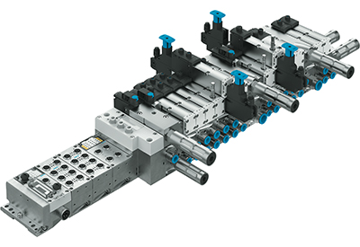
The key to the performance of Nexen’s indexers, including the CRD MR line, is the company’s innovative Roller Pinion System (RPS), which was originally designed for linear motion.
The RPS is a patented linear drive concept that combines the best attributes of existing technologies while eliminating most of their shortcomings. The RPS converts rotary motion into linear motion. The system advances the traditional rack-and-pinion concept by replacing the spur gear teeth with bearing-supported rollers that engage a unique tooth profile in the rack. Instead of the sliding friction of traditional rack-and-pinion systems, the rollers provide smooth rolling friction that converts rotary motion to linear motion with 99 percent efficiency.
The tooth profile of the rack causes the rollers to be loaded in opposition, which eliminates backlash. With this meshing geometry, each roller glides smoothly into the tooth face following a tangent path. The roller does not slap into the teeth, so there’s less noise, vibration and tooth fatigue. In addition, the RPS provides very high positional accuracy, no cumulative error, low-velocity ripple, very high speeds, high rigidity, low maintenance, corrosion resistance and long life. Jams are not an issue because the pinion rollers simultaneously engage several tooth flanks in opposing directions.
To create a ring drive, the linear rack becomes a circular gear. Instead of moving a linear rack side to side, the pinion rotates the gear. The axis of the pinion and the axis of the gear are parallel. A circular plate is bolted atop the gear to create a rotary indexing table.
Unlike some cam-driven rotary indexing systems, the ring drive can start and stop at any incremental position. Engineers can change the motion profile by simply loading a new servo drive program. The ring drive also allows maximum acceleration or deceleration at any point without the risk of damage.